Types of Lines Used in Drawings and Plans
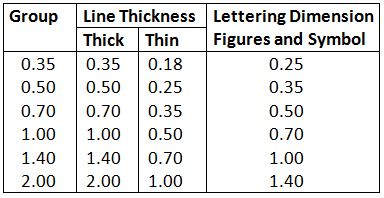
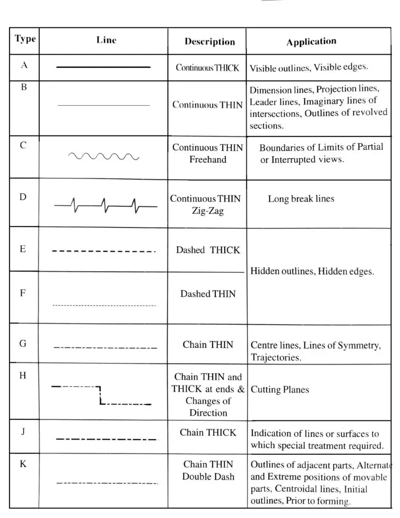
For general engineering drawings, the types of lines recommended past the Bureau of Indian Standards shown in table 2 must exist used. The thickness of the lines must be chosen according to the type and size of the drawing from any of the half dozen groups given in Table 1.
In the case where other types thickness of lines are used for special cases, for example, electric and piping drawings, or if the lines specified in tabular array 2 are used for applications other than those detailed in the concluding cavalcade, the conventions adopted must be explained by notes on the drawing concerned.
Table i: Thickness of lines (All dimensions in mm)
Types of Lines Used in Engineering Drawing
Post-obit are the different types of lines used in engineering drawing:
- A type – Continuos Thick
- B type – Continuous THIN
- C type – Continuous THIN Freehand
- D type – Continuous THIN Zig-Zag
- E blazon – Dashes THICK
- F type – Dashes Thin
- G type – Chain Sparse
- H blazon – Chain THIN and THICK
- J type – Concatenation THICK
- K type – Chain Thin Double Nuance
Read as well: Dimensions and Types of Dimensioning Systems
Tabular array 2: Thickness of Lines
Type A
Outline of Parts
Outline of Parts type lines represent the visible edges of the objects, hence should be outstanding in advent and therefore, are drawn equally bold i.e., thick continuous lines.
Type B
Dimension, Project, Leader, Hatching Lines
Dimension, Projection, Leader, Hatching blazon lines must be drawn thin and continuous. The extension lines for dimensioning should run from the outlines without leaving a gap and extend beyond the dimension lines. This type is also used to draw outlines of adjacent and revolved sections.
Type C
Limits or Boundaries of Partial or Interrupted Views
Limits or Boundaries of Partial or Interrupted Views blazon lines are drawn as continuous, sparse, wavy, freehand lines to represent limits or boundaries of partial or interrupted views.
Type D
Break Lines
Interruption Lines type lines are ruled, brusque, zig-zag thin lines drawn to stand for the breaks.
Type E
Subconscious Lined (Thick)
Hidden Lined (Thick) type lines consist of thick curt dashes, closely and evenly spaced. These lines are fatigued to correspond hidden or invisible edges of the objects.
Type F
Hidden Lines (Sparse)
Hidden Lines (Thin) type lines consist of thin short dashes, closely and evenly spaced. These lines are drawn to represent hidden or invisible edges of the objects. Although THICK lines of Type-E are recommended for representing the subconscious edges, Sparse lines of Type-F are preferred.
Type G
Heart lines, Lines of Symmetry, Trajectories, and Pitch Circles
Centre lines, Lines of Symmetry, Trajectories, and Pitch Circles blazon of lines are long, thin, chain lines with alternately long and curt dashes of proportion ranging from 6:i to 4:1 and evenly spaced. The proportion once selected should exist maintained throughout the drawing. The center lines are extended by a brusque distance beyond the outline. These lines are too fatigued to correspond the lines of symmetry, trajectories, pitch circles. etc,
Type H
Cut Plane Lines
Cutting Airplane Lines are long lines, thickened ar ends and sparse elsewhere, with alternately long and short dashes of proportion ranging from iv:1 to 6:i and evenly spaced. The corners where the section plane charges the direction are fabricated thick for a brusque length.
Type J
Lines to signal Surfaces which crave Additional Treatment
These are long thick lines with alternatively long and short dashes of proportion ranging from six:1 to 4:ane and evenly spaced. These lines are drawn to betoken surfaces, to receive additional treatment like anodizing, plating, etc.
Type One thousand
Lines to indicate Outlines of Adjacent parts, Farthermost positions of Movable Parts, Centroidal lines, Parts situated in front of the Cut Planes, Initial outlines prior to forming.
These are sparse lines with a long and two brusk dashes alternately and evenly placed in the proportion ranging from 6:1 to 4:1. These lines are used to correspond the outlines of next parts, farthermost positions of movable parts in the assembly drawings, parts situated in front of the cutting planes, initial outlines prior to forming, centroidal lines etc.
Download Pdf of this article
Read Next: Dimensions and Types of Dimensioning Systems
That's it, thanks for reading. If you have any questions virtually "Types of Lines" tell us in the comments. If you lot like this article please share with your friends.
Source: https://www.theengineerspost.com/types-of-lines/
Post a Comment for "Types of Lines Used in Drawings and Plans"